Leave A Message
If you are interested in our products and want to know more details,please leave a message here,we will reply you as soon as we can.
Brand:
OEIItem NO.:
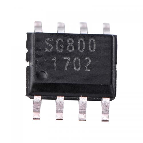
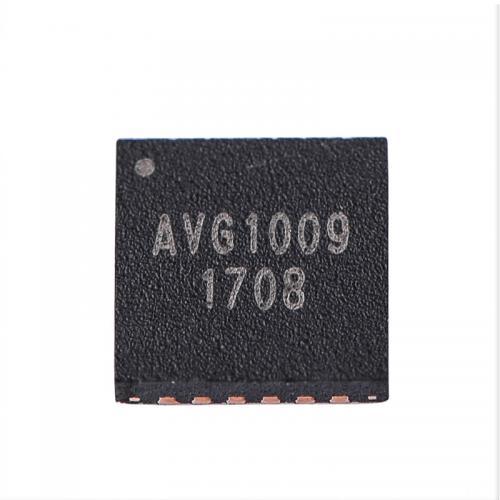
AGC1011Goods Stock:
100000Payment:
TT/LCProduct Origin:
CHINAShipping Port:
SHENZHENLead Time:
According to order quantityProduct Features
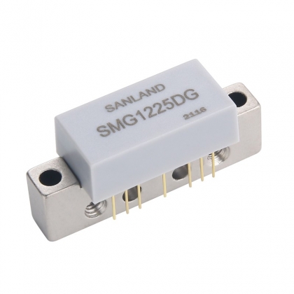
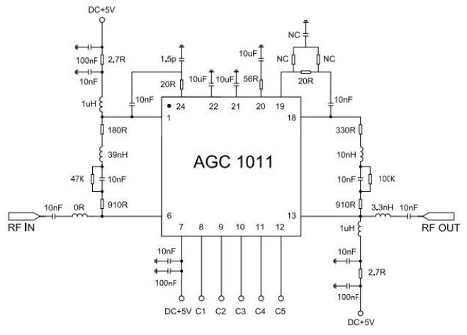
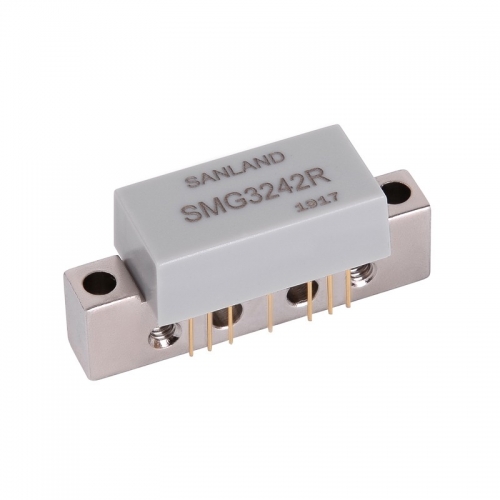
• 40-1218MHz operating frequency range
• Lead-free/RoHS compliant QFN4X4-24L package
Description
|
Parameter |
Specification |
Units |
Notes |
||
|
Min |
Typ. |
Max |
|||
|
Freq |
0.05 |
- |
1.218 |
GHz |
50-1.218GHz |
|
Gain |
- |
41 |
- |
dB |
50-1.218GHz |
|
Gain Control Range |
- |
24 |
- |
dB |
0-24 |
|
P-1dB |
- |
20.5 |
- |
dB |
At 500MHz/5dBm
|
|
OIP3 |
- |
34 |
- |
dB |
At 500MHz/5dBm
|
|
Output return loss |
- |
-15 |
- |
dB |
50-1.218GHz |
|
NF |
- |
0.5 |
0.69 |
dB |
At 500MHz/5dBm |
|
VDD |
- |
5 |
- |
V |
- |
|
IDD |
160 |
180 |
200 |
mA |
Vdd = 5.0V |
|
Test Conditions: VDD=5V, IDD=55mA Typ. OIP3 Tone Spacing=1MHz, Pout per ton=+5 dBm |
|||||
|
TL=25℃, ZS=ZL=50 Ohms |
|||||
Related Tags :


E-mail : info@pinsignal-tech.com
3F/L,Building B1,Glory Technology Industrial Park Baolong 5th Road,LongGang District,Shenzhen City,GuangDong.