Leave A Message
If you are interested in our products and want to know more details,please leave a message here,we will reply you as soon as we can.
Brand:
OEIItem NO.:
AGC1011Payment:
TT/LCProduct Origin:
ChinaShipping Port:
ShenzhenLead Time:
According to Order QuanlityWeight:
30g
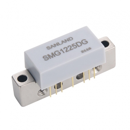
Product Features
● 40-1000MHz operating frequency range.
● High linearity, 60dBc CTB/CSO 135 Channels @+20dBmV/ch.
● 41dB Gain at 55MHz;41.5dB Gain at 1000MHz
● High dynamic gain range, 24dB Gain Control Range, Support 12dBm optical range.
● Single supply, Single +5V Sup
● Low power consumption, 180mA for one RF output at 5V supply voltage.
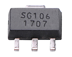
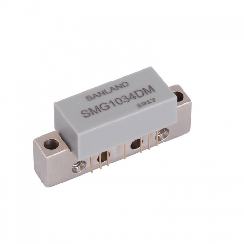
● Lead-free/RoHS compliant QFN4X4-24L package.
Product Performance (Ta=25℃)
Symbol
Parameter1
Units
Frequency
Min.
Typ.
Max.
G
Trans-Impedance
(Max. Gain State)
dB
0.05 GHz
0.87 GHz
1GHz
-
41.0
41.0
41.5
-
G Range
Gain Control Range
dB
-
24
-
P-1dB
dBm
0.45GHz
-
20.5
-
OIP3
Output IP3
dBm
0.45GHz
-
34
-
RL
Output Return Loss
dB
0.05-1 GHz
-
-15
-
IDD
Attenuator Current
mA
VDD=+5V
160
180
200
1. All measurements in a 75 Ohm system, unless otherwise specified.
2. Specified at maximum gain.
3. When the control voltage is changed, the attenuation is changed, Attenuation gain
deviation is ±1.5dB.

Related Tags :

E-mail : info@pinsignal-tech.com
3F/L,Building B1,Glory Technology Industrial Park Baolong 5th Road,LongGang District,Shenzhen City,GuangDong.