Leave A Message
If you are interested in our products and want to know more details,please leave a message here,we will reply you as soon as we can.
Applications:
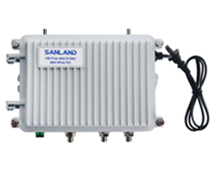
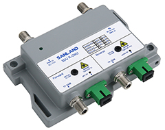
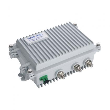
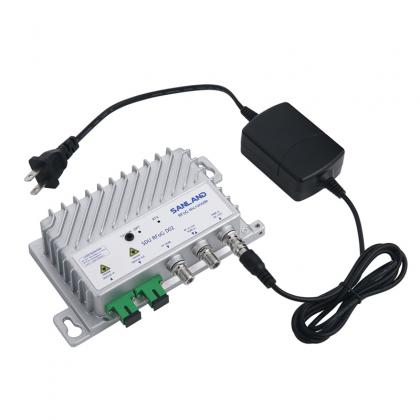
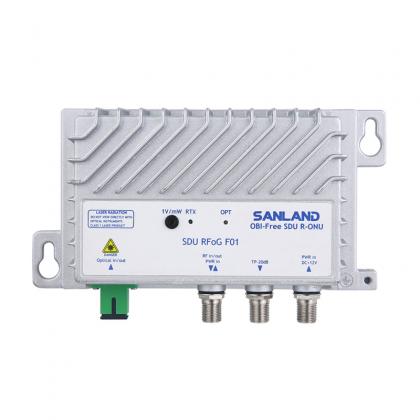
● CATV optical receiver
● CATV Amplifier
● FTTH Network
Brand:
OEIItem NO.:
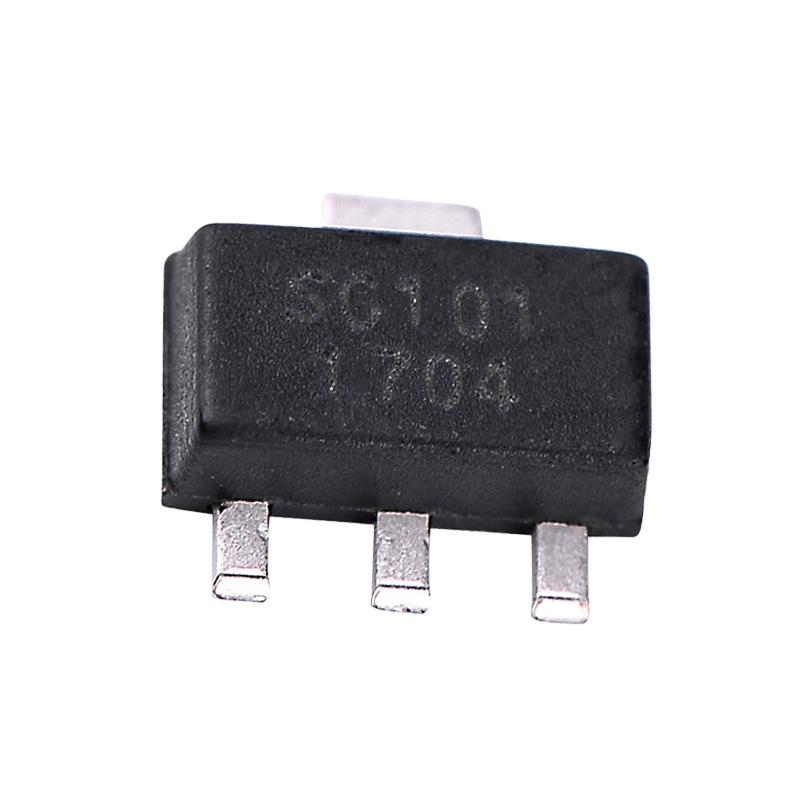
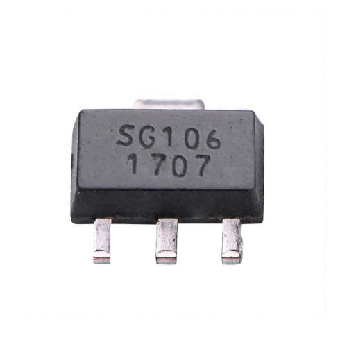
SG101Goods Stock:
100000Payment:
TT/LCProduct Origin:
ChinaShipping Port:
ShenzhenLead Time:
According to Order QuanlityWeight:
250g
Product Features
●High Linearity:+43dBm OIP3
●Wide Bandwidth:50-1000MHz
●P1dB:26dBm
● Low Noise:2.0dB
●Input Output 75ohm Match
● Single Power supply:+8V
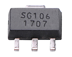
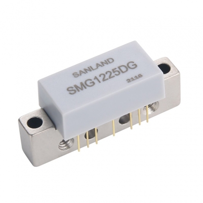
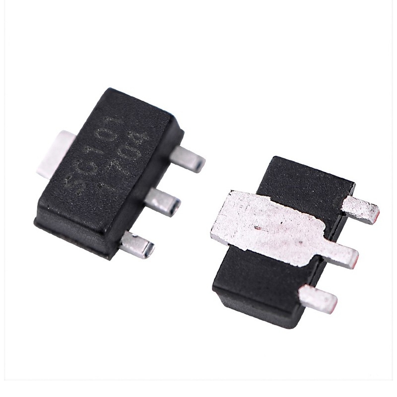
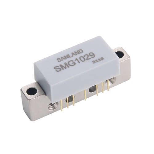
Description:
SG101 mmic amplifiers is GaAs MMIC intended for use in applications requiring high linearity, such as CATV Fiber Receiver and Distribution Amplifiers, and CATV Drop Amplifiers.SG101 is RoHS compliant and offered in SOT89 lead free package.
TYPICAL PARAMETERS(TA=+25℃,VDD=+8VDC,75Ωsystem)
Parameter
Units
Typical
Frequency
MHz
50
500
1000
Noise Figure
dB
2.0
2.0
2.1
Gain
dB
16.5
16
16
S11
dB
-20
-21
-14
S22
dB
-20
-25
-20
Output P1dB
dBm
26
26
26
Output IP3①
dBm
43
43
41
Output IP2②
dBm
54
58
55
CSO③
dBc
-
65
-
CTB③
dBc
-
70
-
Supply Current
mA
-
125
-
Supply Voltage
V
-
8
-
① Tone Spacing=6MHz, Pout per ton=9dBm
② OIP2 is measured at F1+F2 Frequency
③ 79Ch.,Flat,+35dBmV


E-mail : info@pinsignal-tech.com
3F/L,Building B1,Glory Technology Industrial Park Baolong 5th Road,LongGang District,Shenzhen City,GuangDong.