Leave A Message
If you are interested in our products and want to know more details,please leave a message here,we will reply you as soon as we can.
Applications:
● Low Noise Amplifier for CATV, Satellite
● Cable Modem
● FTTH(G-PON,GE-PON)
● Optical node
Brand:
OEIItem NO.:
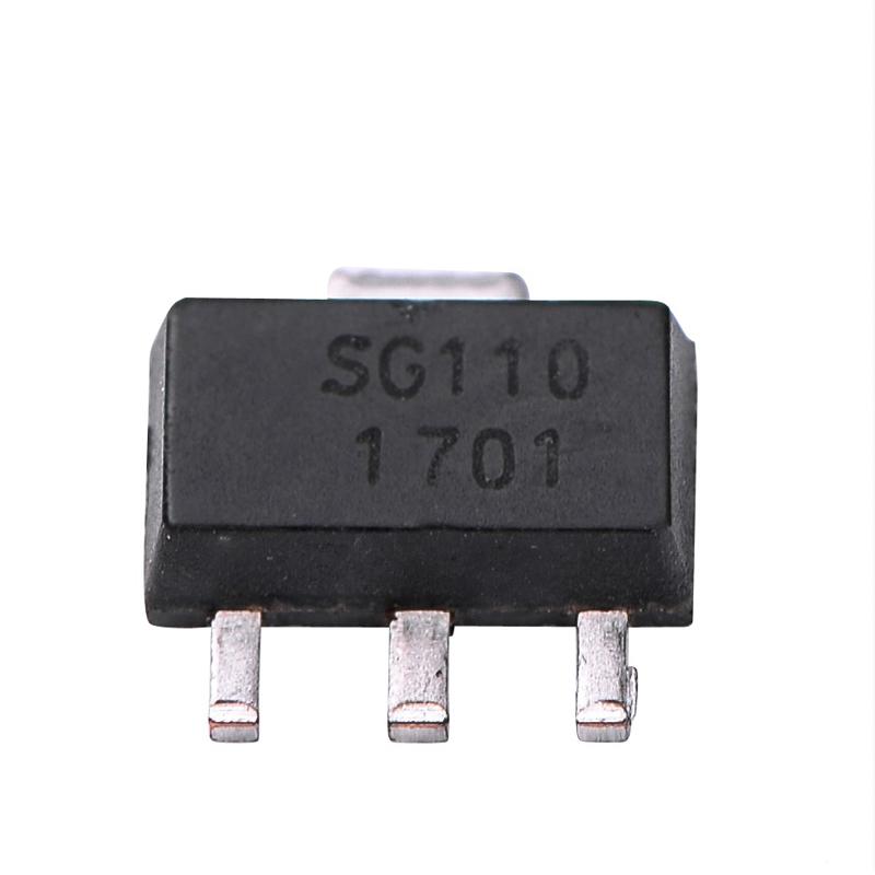
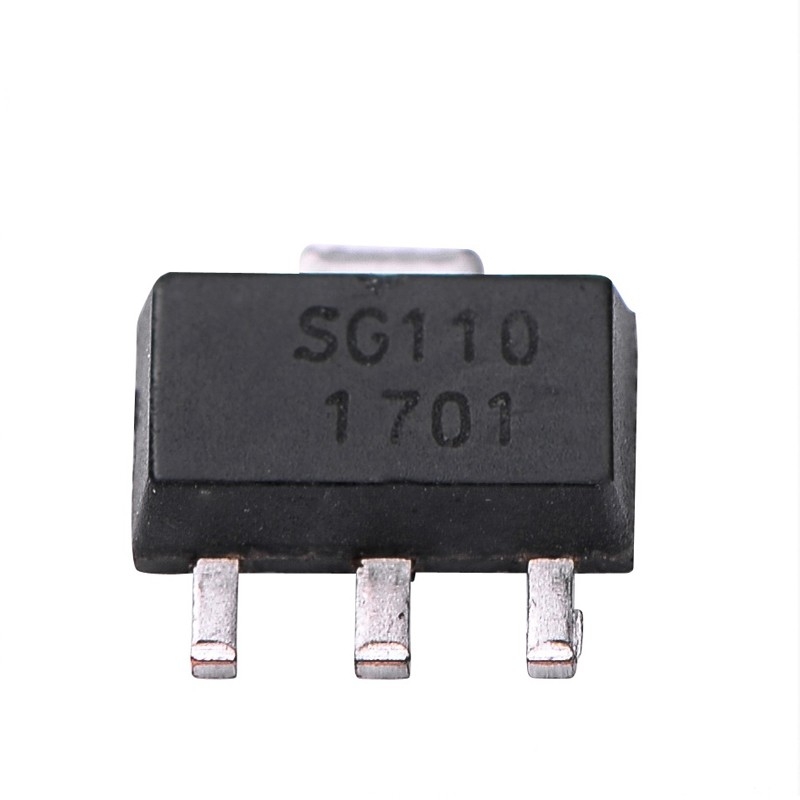
SG110Goods Stock:
100000Payment:
TT/LCProduct Origin:
ChinaShipping Port:
ShenzhenLead Time:
According to Order QuanlityWeight:
250g
Product Features
● Wideband Flat Gain to 1GHz.
● Higher Gain: 24 typ.
● Higher linearity: 35dBm @ 500MHz/5dBm 2tone
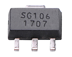
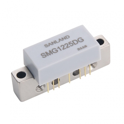
● SOT-89 packag
● -60dBc CSO 135 Channels @ +15dBmV/ch
● -80dBc CTB 135 Channels @+15dBmV/ch
● -83dBc XMD 135 Channels @ +15dBm V/ch
Description:
OEI Technologies’SG110 MMIC power amplifier is a flat gain, high linearity, low noise, 24dB Gain Block with good OIP3 achieved through the use of 0.5um GaAs Enhancement-mode PHEMT process. SG110 is designed as low cost drive amplifiers for many applications including FTTH , CATV System .
Specifications
PARAMETER
UNIT
MIN
TYP
MAX
Condition
Frequency
MHz
5
1000
Gain
dB
-
24
-
30MHz ~ 1000MHz
Gain Flatness
dB
-
0.8
-
5MHz ~ 100MHz
Input Return Loss
dB
-
-12
-
30MHz ~ 1000MHz
Output Return Loss
dB
-
-12
-
Output IP3
dBm
-
35
-
At 500MHz/5dBm 2tone
1dB Compression Point
dBm
-
21
-
At 500MHz
Noise Figure
dB
-
0.9
-
30MHz ~ 1000MHz
CSO
30 ~ 1000MHz
dBc
-
60
-
135 channel, +15dBmV/ch
CTB
dBc
-
70
-
135 channel, +15dBmV/ch
XMOD
dBc
-
80
-
135 channel, +15dBmV/ch
DC Current
mA
-
75
-
Vdd = 5.0V
NOTE
1.Test conditions:Test Freq = 500MHz, T=25℃, Vdd=5V, 75Ω system

Related Tags :

E-mail : info@pinsignal-tech.com
3F/L,Building B1,Glory Technology Industrial Park Baolong 5th Road,LongGang District,Shenzhen City,GuangDong.